


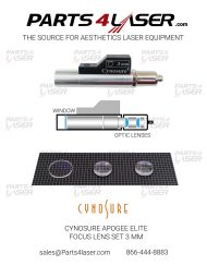
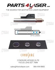


Description
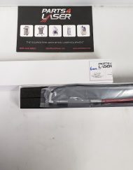
This item contains a set of 2 focus lenses that fit in the machine between laser head and fiber optic cable.
CAOP1257
These are premium quality and custom made focus lenses that are made exactly by the manufacturers requirements. These focus lenses have been applied with AR coating to achieve optimum durability and transmitting of the laser beam. This will create better treatment results and allow your machine to be more time efficient
These lenses will fit the following Candela laser machines:
- GentleLASE
- GentleLASE Plus
- Mini GentleLASE
- Alex Laser Handpiece
LASER RAIL ALIGNMENT Procedure FOCUS LENS ALIGHMENT
CAUTION !!
During this procedure it is possible that the laser may fire, emitting laser radiation.
Therefore SAFETY EYEWEAR must be worn. The eyewear must have an optical
density of at least 5.8 at 745 – 765 nm.
The high voltages present in this system are LETHAL. This procedure must be
performed only by those technicians who are familiar with the precautions required
when working with high voltage systems, and those who have been trained on the
MGL system and its particular hazards.
WARNING!!!!!
BEFORE WORKING NEAR THE HEAD, ALWAYS DUMP THE VOLTAGE BY
SELECTING CHRG DISABLE FROM THE TOGGLE SCREEN, PULSING ONCE,
THEN ENTERING STANDBY. THERE WILL STILL BE ABOUT 150 V ON THE
FLASHLAMP CATHODE, SO THIS SHOULD BE DISCHARGED WITH THE
DISCHARGE STICK. ALWAYS MEASURE THE VOLTAGE AT THE FLASHLAMP
CATHODE BEFORE WORKING ON THE LASER RAIL.
NOTE: If the OPHIR NOVA display is used, be sure the wavelength is set to
YAG or <800, depending on the meter head being used.
1. Remove fiber/delivery system if installed.
2. Install the energy meter bracket, P/N 7122-00-3370, under the front bezel and
install the energy meter onto the bracket.
3. Put on eyewear, go to maintenance mode and on the HV control screen enter
READY.
4. Adjust the voltage for 6.5 – 7.1 J on head detector. Attach black electrical tape
to the alignment plug tool, P/N 7712-00-3363, and imprint the plug’s cross hair
onto the tape with a fine ball point pen. Install the plug into the receptacle facing
the shutter so the cross hair is oriented vertically and horizontally. Put a bag in
front of the plug and pulse the laser in order to make a burn on the tape. If the
cross hair mark gets burned off, re-mark it with a fine pencil or pen.
5. Measure the centering of the burn with respect to the cross hair. Record it
below. It must be 0.5 mm or less vertically and horizontally. Be sure to divide
by 2 if you measure the beam centering by measuring the difference between
the distance from each beam edge to the cross hair. For example, if the top
edge of the beam is 2.0 mm from the cross hair and the bottom edge of the
beam is 2.5 mm from the cross hair, then the difference is 0.5 mm and the
beam is off center vertically by half this, or 0.25 mm.
Vertical de-centering = ___________ mm (£ 0.5 mm)
Horizontal de-centering = _________mm (£ 0.5 mm)
MGentleLASE Laser Rail Alignment Procedure Candela Corporation
Page 4 of 4 Candela Corporation Proprietary 8503-01-0826, Revision A
6. Adjust the voltage until energy is just measured with the energy meter set at its
lowest range (about 1-2 Joules). Record this voltage. Go into STANDBY and
remove the energy meter.
7. Use the following procedure to verify the alignment of the receptacle using the
alignment tool P/N 7122-00-3362 and to perform an alignment if necessary.
Most alignment tools are slightly decentered, so this procedure also reduces the
error caused by this decenter to a negligible value.
7.1 Put a distinguishable mark onto the back of the alignment tool: Apply red or
black “Sharpie” to the proximal end of the fiber on the alignment tool. Insert
the tool into the receptacle with the mark facing up and pulse ONCE.
7.2 Remove the tool and inspect the tool with an eye loupe or a magnifier, keeping
the mark on the tool in the up position. The ink from the “Sharpie” will be gone
where the beam hit.
7.3 Draw a sketch of the beam location.
7.3 Rotate the connector so the mark is facing down and repeat Steps 6.1 to 6.3.
Be sure to look at the end of the fiber with the mark down this time. Sketch
this beam location.
7.4 If the location of the burn has changed from the previous step, then the tool
has a decenter error. The actual beam location is the middle of the two beam
locations. At the actual beam location, if the thickest “Sharpie” band is more
than twice the thinnest band, then the receptacle must be aligned or replaced.
To align:
· Loosen the two inner (in the slotted holes) 4-40 socket head
screws securing the lens housing assembly to the fiber receptacle
block ¾ turn each. Slightly adjust one of the two set screws,
located on the top (vertical axis) and left (horizontal axis) side of
the fiber receptacle block (do not touch the ball plunger screw on
the right side of the block). Adjust the set screw in the desired
direction (ex: if burn spot is off to the left on the tool, adjust the lens
housing towards the right (looking at the beam input side of the
fiber receptacle)).
· Perform the “Sharpie” burn and re-adjust until alignment is
acceptable.
· Tighten the two 4-40 screws evenly and repeat the two “Sharpie”
burns to make sure nothing has shifted.
8. Clean the fiber alignment tool’s tip with a cotton applicator and solvent when
finished and replace caps to both ends of the tool.
9. Press Charge enabled so it is not highlighted on the HV Ctrl screen and pulse
once to discharge the caps. Go to STANDBY.
10. Install the laser rail dust cover
FOCUS LENS REPLACEMENT
NOTE: Exercise extreme care. Cleanliness of optics is essential. Refer to Service
Procedure 8503-01-0060 for optic cleanliness. Refer to drawings 7122-00-3298, 7122-00-
3300 and 7122-00-3325 for specific details.
CAUTION: The high voltages present in this system are LETHAL. This procedure
must be performed only by those technicians who are familiar with the precautions
required when working with high voltage systems, and those who have been trained
on the MGL system and its particular hazards.
WARNING!!!!!
BEFORE WORKING NEAR THE HEAD, ALWAYS DUMP THE VOLTAGE BY
SELECTING CHRG DISABLE FROM THE TOGGLE SCREEN, PULSING ONCE,
THEN ENTERING STANDBY. THERE WILL STILL BE ABOUT 150 V ON THE
FLASHLAMP CATHODE. THIS MUST BE DISCHARGED WITH THE
DISCHARGE STICK. ALWAYS MEASURE THE VOLTAGE AT THE FLASHLAMP
CATHODE BEFORE WORKING ON THE LASER RAIL.
1. Remove the fiber from the fiber receptacle. Remove the top cover. Remove the
laser rail dust cover.
2. Remove the shutter. Temporarily remount the shutter with one screw above fiber
focusing assy in the dust cover mounting hole.
3. Remove screws holding the fiber receptacle to the rail.
4. Disconnect the microswitch.
5. Remove the fiber receptacle.
6. Loosen the two set screws (figure 1), then
loosen the two positioning screws on the
focus lens housing. Remove the Four rear
screws that secure the focus lens housing
(7122-00-3325) intothe fiber receptacle
assembly. Pay attention to component
order when disassembling.
Figure 1
Set screws
Four rear
MGentleLASE Focus Lens Replacement Procedure Candela Corporation
Page 4 of 5 Candela Corporation Proprietary 8503-01-0827, Revision A
7. Removing the Lens:
· Remove Jam nut.
· Pry out the first lens with Exacto knife, or turn the barrel upside down and tap
it sharply onto a clean piece of paper on a table.
· Pry out the first o-ring.
· Remove the spacer.
· Push out the second lens.
8. Replace or clean optics and o-rings as needed.
9. Re-assemble per drawing 7122-99-3325, Fiber Receptacle Assembly and procedure:
A. Install first o-ring, Item 2.
B. Install first lens, Item 3, using Insertion tool 1301-00-8121) or a 15 mm
distance gauge (When usng a 15mm distance gauge, you must press down
to insert lens then rotate 90º and repress down to insure lens is flat in
housing.). Push down on insertion device to seat lens.
C. Install Spacer Item 4 in orientation shown.
D. Install the Second o-ring, Item 2. Push the o-ring into the groove with a plastic
tool or the wooden end of a cotton applicator.
E. Install the second lens, Item 3 in the orientation shown, using insertion tool or
a 15 mm distance gauge. Push down on insertion device to seat lens.
F. Screw the jam nut Item 5 in orientation shown into the housing until it stops.
Back out nut one turn and tap the side of the housing a few times to properly
center the lenses. Tighten the nut so that it is snug. DO NOT OVER
TIGHTEN.
G. Install the lens housing assy (item 2) into the receptacle block in the
orientation shown. Roughly align (rotate) the lens housing so that the
housing’s (2) threaded 4-40 tapped holes are aligned diagonally with the
receptacle block’s threaded 4-40 holes.
H. Hold the receptacle block vertically, snout end facing down, lens housing
facing up. Gently push the lens housing diagonally so that it is resting flat
inside the block.
I. Visually inspect the centering of the lens housing inside the receptacle block.
The space (gap) between the outer diameter of the lens housing and the inner
diameter of the receptacle block should be even all the way around. Adjust set
screws (Figure 1) until the space (gap) is even.
Candela Corporation MGentleLASE Focus Lens Replacement Procedure
8503-01-0827, Revision A Candela Corporation Proprietary Page 5 of 5
J. Attach the plate (item 5), in orientation shown, onto the lens housing with
hardware (2 ea.- items 6 and 7). Fully tighten the screws, then back out ½
turn each.
K. Carefully rotate the plate (with housing attached), if needed, so that the plate’s
(4) mounting holes are aligned with the (4) threaded holes in the receptacle
body. Secure plate onto block with screws (4 ea.- item 6). Fully tighten
screws.
10. Install the receptacle onto the rail.
11. Perform a Fiber Alignment Verification per the Service procedure 8503-01-0826
Parts4laser is not affiliated, associated, authorized, endorsed by, or in any way officially connected with Candela their affiliates. Any logos and trademarks of third parties that may be found on our website are registered trademarks of their respective owners. The use of any trademark is for identification and reference purposes only and does not imply any association with the trademark holder.